Arrow spine is a critical component of archery accuracy. In this article, we will show, step by step, how to make a spine tester out of very obtainable material. When you are finished, you’ll have a spine tester that will help you measure spine of any arrow and narrow down the shafts that you will select for your competitive archery needs.
The arrow spine tester in this tutorial can measure the spine of wooden arrows (arrow braced at 26 inches with the weight suspended at the 13 inch center) and modern carbon and aluminum arrows (arrow braced at 28 inches with the weight suspended at the 14 inch center).
Below are the materials and tools you’ll need for making this arrow spine tester followed by our step by step instructions. When it is completed, it should look like this. Good luck!
![]()
Materials and tools needed for making an arrow spine tester
Materials needed
- Machinist’s dial indicator – $17 at Harbor Frieght
- 2 lb lead weight – $5 on ebay
- 1″ x 8″ x 3′ oak board – $12.50 at Menards or Home Depot
- (30) #8 x 3/4″ wood screws – $2 at Menards or Home Depot
- (4) #12 zinc flat washers – $0.30 at Menards or Home Depot
- (1) 1/4″ x 1″ phillips head bolt
- (1) 1/4″ nut
- (1) 1/4″ lock washer
- (4) 2″ x 5/8″ zinc corner braces – $0.75 each at Menards or Home Depot
- (2) 2-1/2″ x 5/8″ zinc corner braces – $0.78 at Menards or Home Depot
- (2) 1″ x 1/2″ zinc corner braces – $0.52 at Menards or Home Depot
- (4) Premium skateboard/roller blade bearings – $7.50 ($15 for an 8 pack)
Total material cost = $50
Tools needed
- Power miter saw or circular saw
- Corded or cordless drill
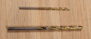
- 1/16″ drill bit
- 1/8″ drill bit
- Phillips bit or phillips screwdriver
- Measuring tape
- Pencil
- Speed square
How to Make an Arrow Spine Tester
- Rip your 1″ x 8″ x 3′ oak board so your cut off is 2-1/2″. After this cut, you will have a 2-1/2″ x 3′ and a 4-3/4″ x 3′ board.
- Cut (2) 4-1/2″ and (1) 8″ long pieces from your 2-1/2″ x 3′ board.The 4-1/2″ pieces will be for the roller support boards.
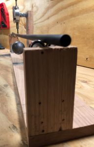
The 8″ piece will be for dial support board.** The roller support board height is determined by your 2 lb weight height. For our arrow spine tester, we used a “canon ball” style weight that was purchased off eBay. If your weight is taller, you will have to adjust. Here is the measurement of our weight (about 2-1/2 inches).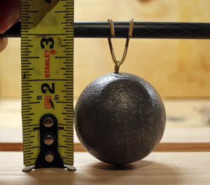
- Mark the center of the top of both roller supports (2-1/2″ x 4-1/2″ boards). From the center mark, 7/16″ each way and make a mark. Your new marks should be 7/8″ apart.
- Make a mark 3/16″ down from the top of the board on your marks.
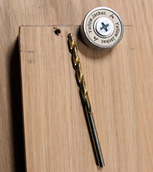
- Drill the marks with the 1/16″ drill bit. You are near the top of the board so take your time drilling these holes.
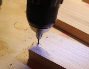
- Drill out the holes with the 1/8″ bit.
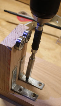
- With the roller bearings, washers, and #8 wood screws, install your rollers.
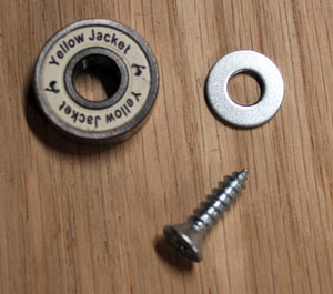
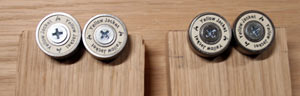
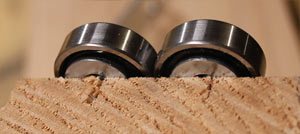
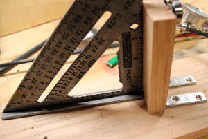
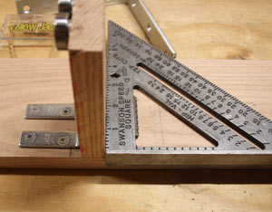
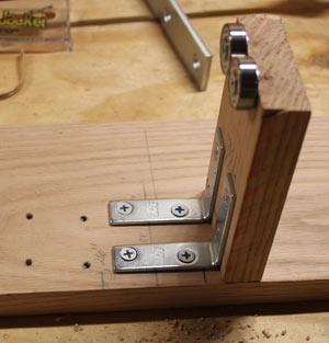
You’ll notice wood being forced up at the screws. This is due to using #10 wood screws instead of #8 wood screws. - Stand up one roller support board and place (2) 2″ x 5/8″ zinc corner braces against the base. Use the speed square to verify that your corner braces are indeed at 90°. If they are not exactly at 90°, adjust them. Mark the holes on the roller support board.
- Drill out the marked holes.
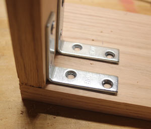
- Install the corner braces with (4) #8 wood screws.
- Repeat steps 8 through 10 with the second roller support board.
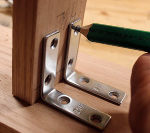
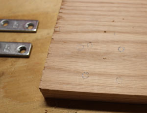
- Hold one roller support board in place at the corner of 4-3/4″ x 3′ board (side closest to you) and mark the 4 remaining holes.
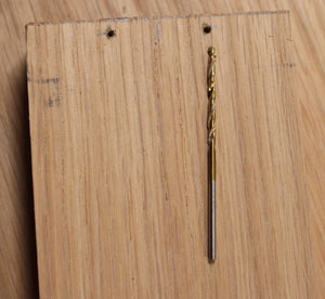
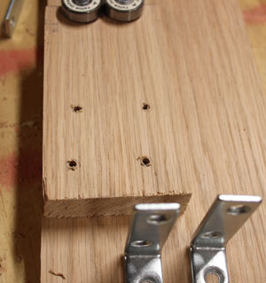
- Drill the 4 holes with the 1/16″ and 1/8″ drill bits.
- Install the roller support board. Use an additional bit extension for easier installation of the 2 screws closest to the roller support board.
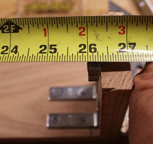
- Measure the distance from the back of the roller support board to the outside of the rollers. Transfer that mark (1-1/16″ in our case) to the base board.

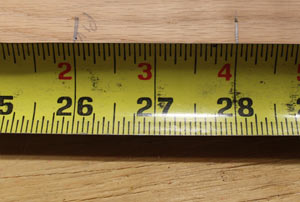
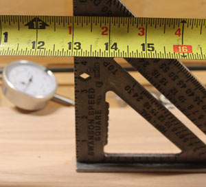
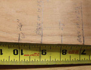
- From the transferred mark, we are going to make 4 additional marks. Their distances will be 13″ (wooden arrow testing center mark), 14″ (modern arrow testing center mark), 26″ (inner edge of roller for wooden arrow testing), and 28″ (inner edge of roller for modern arrow testing). You can verify your marks by holding your tape measure horizontally to the edge of the roller and checking their location with a speed square.
- From the 26″ and 28″ inch mark, add the thickness of the board and rollers (in our case it was 1-1/16″) and mark the board. This should be the back of your roller support board.
- Hold the second roller support board on the “back of board” mark and square it with the speed square.
- Verify that the inside edge of the rollers are exactly 26 inches from the inside edge of the opposite rollers.
- Mark the corner brace holes on the base board, drill the pilot holes, and install the screws.
- Repeat this process at the 28 inch mark.
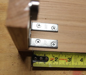
- Stand up the dial support board and place (2) 2-1/2″ x 5/8″ zinc corner braces against the base and exactly 1 inch apart from each other and centered. Use the speed square to verify that your corner braces are indeed at 90°. If they are not exactly at 90°, adjust them. Mark the holes on the dial support board. If this proves to be difficult, screw the corner braces to a board for easier marking.
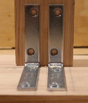
The measurement from center to center of the corner braces should be exactly 1 inch. - Drill out the holes and install (4) #8 wood screws to secure the corner braces to the dial support.
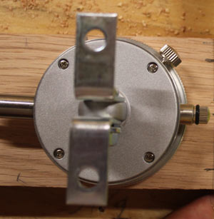
- With the 1/4″ x 1″ phillips head bolt, 1/4″ lock washer, and 1/4″ nut, secure the (2) 1″ x 1/2″ zinc corner braces to the back of the machinist’s dial indicator.
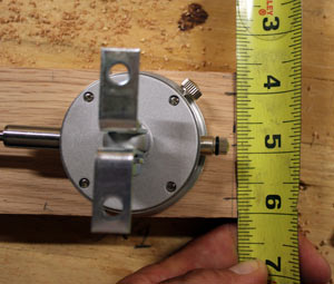
- Locating the installation height of the machinist’s dial indicatorMethod #1 – Using mathPlace a large diameter arrow on both sets of rollers and measure to the top of the arrow from the base board. Your machinist’s dial indicator will have a moving rod that has about 1-1/16″ of travel. You will want the rod to be extended 1/4″ when it makes contact with the top of the arrow. Measure from the corner brace holes to the dial’s moving rod when it is exposed 1/4″. Add both numbers together and that is the height of your dial mounting screws. Mark the dial support board accordingly.
Method #2 – Holding the dial in place
Place a large diameter arrow on both sets of rollers. While holding the dial squarely against the dial support board, move it towards the arrow. With the aid of a tape measure, figure out where it should be mounted when 1/4″ inch of the exposed dial shaft would contact the top of the arrow. Mark the dial support board accordingly.
Method #3 – Use our numbers
If you bought a 1 In. Travel Machinist’s Dial Indicator by Pittsburgh at Harbor Freight, you should be able to use our numbers. Your measurement from the base board to the mounting screws will be 7-1/2″.
- Center your dial/brace assembly on the dial support board and mark your holes.
- With the 1/16″ and 1/8″ drill bits, drill the pilot holes.
- Disassemble the machinist’s dial indicator from the corner braces and install the braces to the dial support board.
- Reassemble the machinist’s dial to the corner braces.
- With an arrow loaded on the rollers and your machinist’s dial indicator at the 13 inch mark, move your machinist’s dial indicator until the roller head of its movable rod is in the center of the arrow.
- Mark the corner brace holes at the bottom of the dial support board.
- With the 1/16″ and 1/8″ drill bits, drill the pilot holes into the base board.
- Install (4) #8 wood screws to secure the dial support board.
- Repeat this process at the 14 inch mark. Since the dial support bottom corner braces are exactly 1 inch apart, you will be able to use 2 screw holes form the 13 inch installation.
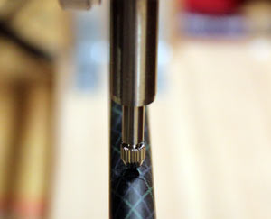
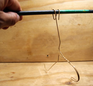
- With a clothes hanger and a large shaft arrow, fashion a hook that your weight can hang from.
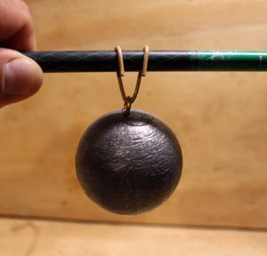
- Attach your weight to the hanging hook.
Congratulations! You are now done building your arrow spine tester. Now let’s take a look at how to use this arrow spine tester.
 How to Use an Arrow Spine Tester
To use the arrow spine tester, follow these steps:
- Install the dial support board and rollers at the proper distance for the arrow you plan on testing (13″ and 26″ locations for wooden arrows, 14″ and 28″ locations for modern carbon and aluminum arrows).
- Retract the dial’s movable rod and load your arrow.
- Lower the rod’s roller point until it makes contact with the arrow.
- Adjust the rotatable dial face until “0” is at the contact with arrow point.
- Adjust your lead weight. For wooden arrows, the weight should weigh 2 lbs. and for modern arrows it should weigh 1.94 lbs (880 grams). You can fine tune the weight’s weight by drilling holes to lower the weight and adding a screw to a hole to bring it back up to weight.
- Position your weight on the arrow around the dial’s rod tip.
- Slowly lower the weight while watching the dial. Count the revolutions. For every revolution, it is 0.100 of an inch. If the dial made 3 revolutions plus 50, the spine of that arrow would be 0.350.
What you do from here is up to you. Thanks for reading this tutorial on how to make an arrow spine tester. For more information on arrow spine, visit our arrow spine page.